Famicom cartridge dimensions: Difference between revisions
mNo edit summary |
(Update outline for HVC-TxROM) |
||
| Line 24: | Line 24: | ||
=== HVC-TxROM === | === HVC-TxROM === | ||
==== Cartridge PCB outline ==== | ==== Cartridge PCB outline and card edge dimensions ==== | ||
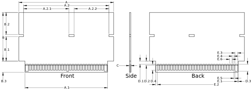
This outline is based on measurements from a HVC-TGROM-01 cartridge, so it should be compatible with any cartridge shell that supports any HVC-AxROM / FxROM / PxROM / SxROM / TxROM/ PCB or similar/bigger. These measurements should approximate closely, as it assumes a 1/128 inch grid. | This outline is based on measurements from a HVC-TGROM-01 cartridge, so it should be compatible with any cartridge shell that supports any HVC-AxROM / FxROM / PxROM / SxROM / TxROM/ PCB or similar/bigger. These measurements should approximate closely, as it assumes a 1/128 inch grid. | ||
Each cartridge type varies in how the 60 pin card edge is implemented. The pin pitch is 2.54mm, with 2 rows of 30 pads. Each pad may be uniform in dimensions, or slightly thicker and longer for power/ground. This outline is based on measurements from a HVC-TGROM-01 cartridge, with bigger pads to accommodate power. Note that this outline also details where the soldermask ends for the card edge. | |||
[[File:HVC-TGROM-01-board.svg|frame|center|HVC-TGROM-01 PCB outline and dimensions]] | [[File:HVC-TGROM-01-board.svg|frame|center|HVC-TGROM-01 PCB outline and dimensions]] | ||
=== HVC-ExROM === | === HVC-ExROM === | ||
Revision as of 09:39, 21 December 2021
This page documents the dimensions of common Famicom cartridges, including their cartridge shell and their corresponding PCB type. The source files are open-source and available on Github.
TODO: identify more cartridge shell forms
Famicom cartridge shell outline
Small cartridge form
HVC-TxROM
TODO: measure and publish dimensions
HVC-NROM/CNROM
TODO: measure and publish dimensions
Large cartridge form
HVC-ExROM
TODO: measure and publish dimensions
Miscellaneous cartridge forms
TODO: document and measure other forms
Famicom cartridge PCB outline
HVC-TxROM
Cartridge PCB outline and card edge dimensions
This outline is based on measurements from a HVC-TGROM-01 cartridge, so it should be compatible with any cartridge shell that supports any HVC-AxROM / FxROM / PxROM / SxROM / TxROM/ PCB or similar/bigger. These measurements should approximate closely, as it assumes a 1/128 inch grid. Each cartridge type varies in how the 60 pin card edge is implemented. The pin pitch is 2.54mm, with 2 rows of 30 pads. Each pad may be uniform in dimensions, or slightly thicker and longer for power/ground. This outline is based on measurements from a HVC-TGROM-01 cartridge, with bigger pads to accommodate power. Note that this outline also details where the soldermask ends for the card edge.
HVC-ExROM
TODO: measure and publish dimensions
HVC-NROM/CNROM
TODO: measure and publish dimensions
