File:Neswires.jpg: Difference between revisions
From NESdev Wiki
Jump to navigationJump to search
Abridgewater (talk | contribs) (Added best-effort transcription and translation for much of the Japanese text.) |
No edit summary |
||
| Line 1: | Line 1: | ||
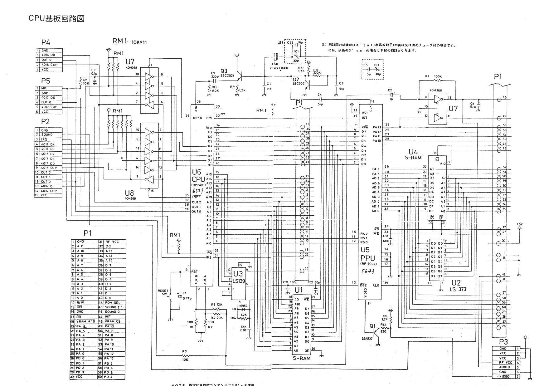
This is a modified version of [https://www.nesdev.org/Ntd_8bit.jpg this Famicom wiring diagram], altered to depict the NES (unsure if a frontloader or toploader). | |||
Writing at top-left says: | Writing at top-left says: | ||
Latest revision as of 11:49, 8 August 2023
This is a modified version of this Famicom wiring diagram, altered to depict the NES (unsure if a frontloader or toploader).
Writing at top-left says:
CPU基板回路図
Possible translation:
CPU board schematic
Writing at top-right appears (taking some license, given the low scan resolution) to say:
注)回路図の破線部はX'tal(水晶振動子)が賛13⁄64又は青のチューブ付の場合です。
なお、灰色のX'talの場合は下記の回路となります。
Possible translation:
Note)The broken-line section of the schematic is for the situation with X'tal(crystal oscillator) marked 13/64 or enclosed in blue tubing.
Yet, for a gray X'tal situation it becomes the circuit below.
Writing at bottom is clearly truncated, but appears to concern the use of 0.01uF capacitors ("condenser").
File history
Click on a date/time to view the file as it appeared at that time.
| Date/Time | Thumbnail | Dimensions | User | Comment | |
|---|---|---|---|---|---|
| current | 21:56, 21 September 2021 | 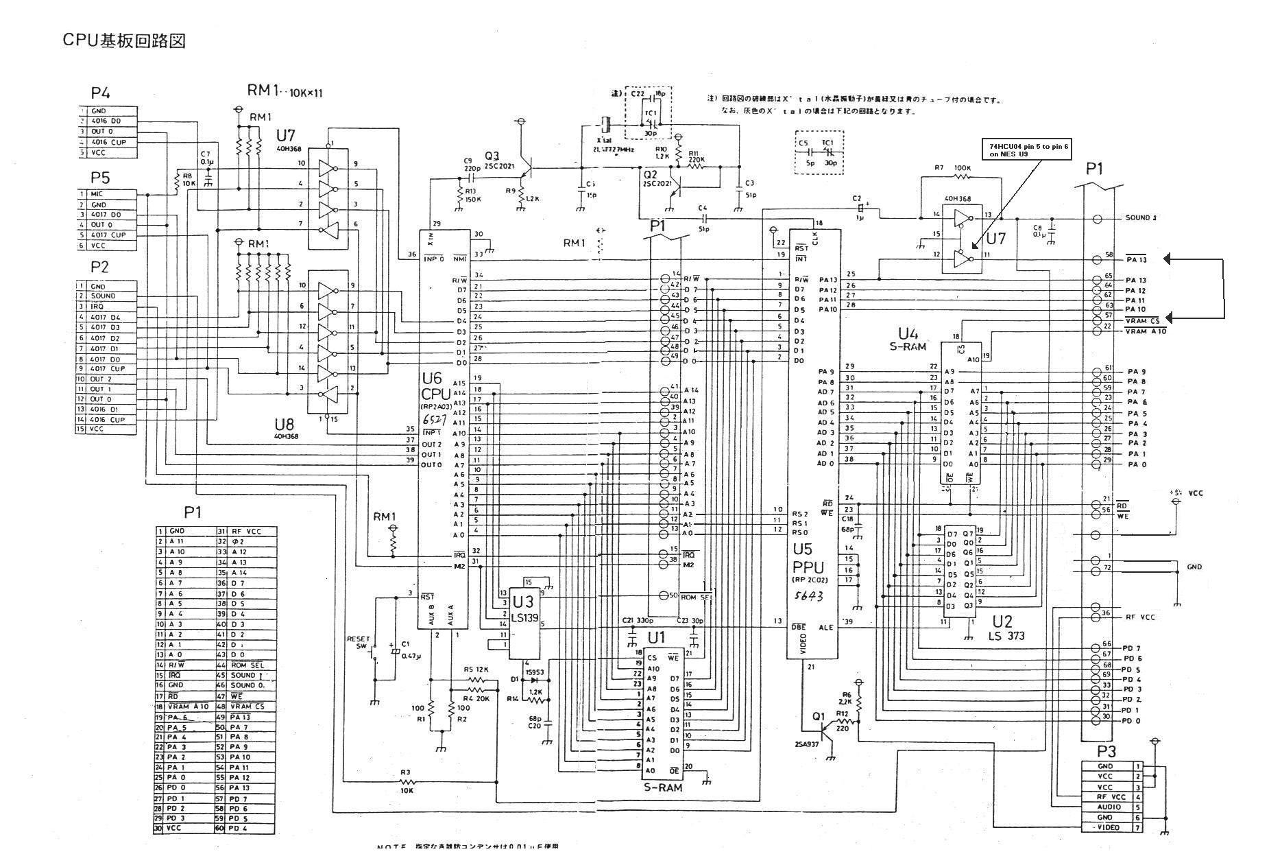 | 1,870 × 1,245 (338 KB) | >Maintenance script | == Summary == Importing file |
You cannot overwrite this file.
File usage
The following 3 pages use this file: