File:Pal video timing.png: Difference between revisions
From NESdev Wiki
Jump to navigationJump to search
(A visualization of the PAL PPU's video output signal, using different colors to denote each part of the signal. Based on File:Ntsc_video_timing.png. The video output of the PPU is delayed by 1 pixel clock. In addition, the active video portion is delayed by another 1 pixel clock. Cycle 0, scanline 0 according to the [https://www.nesdev.org/wiki/File:Ppu.svg PPU Frame Timing Diagram] is marked by the black pixel. * Cyan is the horizontal blanking pulse * Dark blue is the "back porch" aft...) |
(Reword description; fix hyperlink) |
||
| Line 1: | Line 1: | ||
== Summary == | == Summary == | ||
A visualization of the PAL PPU's video output signal, using different colors to denote each part of the signal. Based on [ | A visualization of the PAL PPU's video output signal, using different colors to denote each part of the signal. Based on [https://www.nesdev.org/wiki/File:Ntsc_video_timing.png Ntsc_video_timing.png]. | ||
The video output of the PPU is delayed by 1 pixel clock. In addition, the active video portion is delayed by another 1 pixel clock. Cycle 0, scanline 0 according to the [https://www.nesdev.org/wiki/File:Ppu.svg PPU Frame Timing Diagram] is marked by the black pixel. | The video output of the PPU is delayed by 1 pixel clock in relation to the working PPU memory. In addition, the active video portion is delayed by another 1 pixel clock. Cycle 0, scanline 0 according to the [https://www.nesdev.org/wiki/File:Ppu.svg PPU Frame Timing Diagram] is marked by the black pixel. | ||
* Cyan is the horizontal blanking pulse | * Cyan is the horizontal blanking pulse | ||
Revision as of 20:28, 11 April 2023
Summary
A visualization of the PAL PPU's video output signal, using different colors to denote each part of the signal. Based on Ntsc_video_timing.png.
The video output of the PPU is delayed by 1 pixel clock in relation to the working PPU memory. In addition, the active video portion is delayed by another 1 pixel clock. Cycle 0, scanline 0 according to the PPU Frame Timing Diagram is marked by the black pixel.
- Cyan is the horizontal blanking pulse
- Dark blue is the "back porch" after HBlank
- Yellow is the colorburst signal
- Red is the visible output region, including the left and right border
- Bright red is where the background and sprites are actually visible
- Dark red is where the border crops into the active video output
- Orange is the "front porch" before HBlank
- Magenta is the vertical blanking pulse
- Dark green is the surrounding black border, vertical blanking region, and the sync separator
File history
Click on a date/time to view the file as it appeared at that time.
| Date/Time | Thumbnail | Dimensions | User | Comment | |
|---|---|---|---|---|---|
| current | 05:18, 12 April 2023 |  | 341 × 312 (1 KB) | Persune (talk | contribs) | Added one missing scanline |
| 20:25, 11 April 2023 | 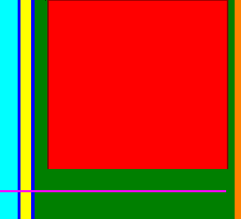 | 341 × 311 (1 KB) | Persune (talk | contribs) | A visualization of the PAL PPU's video output signal, using different colors to denote each part of the signal. Based on File:Ntsc_video_timing.png. The video output of the PPU is delayed by 1 pixel clock. In addition, the active video portion is delayed by another 1 pixel clock. Cycle 0, scanline 0 according to the [https://www.nesdev.org/wiki/File:Ppu.svg PPU Frame Timing Diagram] is marked by the black pixel. * Cyan is the horizontal blanking pulse * Dark blue is the "back porch" aft... |
You cannot overwrite this file.
File usage
The following page uses this file: