User:Ulfalizer
Misc. timing stuff brought together in one place
Reads and writes
Read (LDA $1234, NOP)
Tick-by-tick from http://nesdev.org/6502_cpu.txt interleaved with steps from Visual 2A03:
 #  address R/W description
--- ------- --- -------------------------------------------------
 1    PC     R  fetch opcode, increment PC
    ab    db  rw  pc    phi2
    0000  ad  1   0000  0
    0000  ad  1   0000  1
 2    PC     R  fetch low byte of address, increment PC
    ab    db  rw  pc    phi2
    0001  34  1   0001  0
    0001  34  1   0001  1
 3    PC     R  fetch high byte of address, increment PC
    ab    db  rw  pc    phi2
    0002  12  1   0002  0
    0002  12  1   0002  1
 4  address  R  read from effective address
    ab    db  rw  pc    phi2
    1234  00  1   0003  0
    1234  00  1   0003  1
Write (LDA #$AB, STA $1234, NOP)
Tick-by-tick from http://nesdev.org/6502_cpu.txt interleaved with steps from Visual 2A03:
 #  address R/W description
--- ------- --- ------------------------------------------
 1    PC     R  fetch opcode, increment PC
    ab    db  rw  pc    phi2
    0002  8d  1   0002  0
    0002  8d  1   0002  1
 2    PC     R  fetch low byte of address, increment PC
    ab    db  rw  pc    phi2
    0003  34  1   0003  0
    0003  34  1   0003  1
 3    PC     R  fetch high byte of address, increment PC
    ab    db  rw  pc    phi2
    0004  12  1   0004  0
    0004  12  1   0004  1
 4  address  W  write register to effective address
    ab    db  rw  pc    phi2
    1234  12  0   0005  0
    1234  ab  0   0005  1
Read/write observations
- Address bus and rw changes right away (during φ1).
- Values appear to be read during φ2 (dbx pins buffered on cclk), and db changes during φ2 for writes too.
- Clocks section of tutorial.
Interrupts
Sampled on the falling edge of φ2. IRQ detection depends on nodes nnT2BR (branch-related) and 646 (maybe a "sampling points" signal) being low.
Visual 6502 links
Smallest IRQ assertion interval that will trigger an IRQ for LDA #FF: http://visual6502.org/JSSim/expert.html?logmore=Execute,irq,IRQP,State,nnT2BR,646&a=0&d=58A9FF1890FE&irq0=5&irq1=6&steps=20
Ditto for LSR $AB: http://visual6502.org/JSSim/expert.html?logmore=Execute,irq,IRQP,State,nnT2BR,646&a=0&d=5846AB1890FE&irq0=11&irq1=12&steps=20
Ditto for LSR $AB with NMI instead of IRQ: http://visual6502.org/JSSim/expert.html?logmore=Execute,nmi,~NMIG,State&a=0&d=58461890FE&nmi0=11&nmi1=12&steps=20
M2 duty cycle
The M2 duty cycle is 5/8 - forum post and CPU pin-out page. Low for 9/8 PPU cycles, high for 15/8 PPU cycles. Low for 4.5 master cycles, high for 7.5 master cycles. Low for ~210 ns, high for ~349 ns.
PPU interface
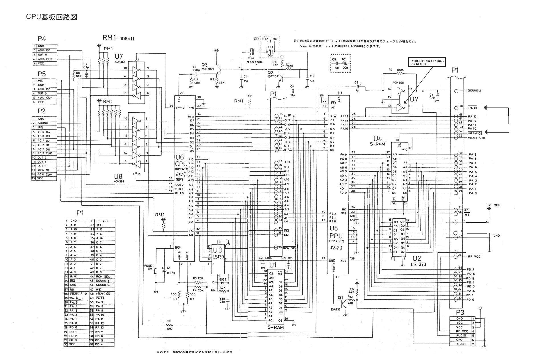
Input map:
Binding         | Interpretation
----------------+--------------------------------------
0   -> 15       | 0     -> /Enable second demultiplexer
a15 -> 13       | a15   -> A_1b
a14 -> 3        | a14   -> A_1a
a13 -> 2        | a13   -> A_0a
M2  -> 14       | M2    -> A_0b
11  -> 1        | /O_1b -> /Enable first demultiplexer
9   -> /ROM SEL | /O_3b -> /ROM SEL
5   -> /DBE     | /O_1a -> /DBE
4   -> RAM CS   | /O_0a -> RAM CS
Input/output map:
Inputs   | Outputs
---------+----------------
E  A0 A1 | O_0 O_1 O_2 O_3
---------+----------------
1  x  x  | 1   1   1   1
0  0  0  | 0   1   1   1
0  1  0  | 1   0   1   1
0  0  1  | 1   1   0   1
0  1  1  | 1   1   1   0
Hence:
ROM SEL = M2 && a15
<Enable first demultiplexer> = M2 && !a15
DBE = <Enable first demultiplexer> && !a14 && a13
RAM CS = <Enable first demultiplexer> && !a14 && !a13
Summary:
When M2 high,
A15-13 | Signal
-------+--------
1xx    | ROM SEL
001    | DBE
000    | RAM CS
- rw signal together with ab lines directly generates signals like /r2002.
- _io_ce follows inverted M2.
- vbl_flag is set via a vpos was 241 and vpos is not 241 comparison. Goes high at hpos = 1 during at pclk0.
- The set_vbl_flag signal is high during pclk0 of vpos=241/hpos=1.
- spr0_hit goes high at tick x+2, during pclk1. Reading uses same _io_ce behavior as vbl_flag.
- spr_overflow reading behavior just like spr0_hit. TODO: set timing.
- $2005/$2006 and $2000 nametable bits writes use the same timing.
Timing charts
Around VBL flag setting:

               set_vbl_flag signal active during this interval
                                  |
                                 [++]
Master: 0101010101010101010101010101010101010101010101010101010101010101010101010
PPU:     [p0][p1][p0][p1][p0][p1][p0][p1][p0][p1][p0][p1][p0][p1][p0][p1][p0][p1]
CPU:      [  Low  ][     High    ]                                 -> 0, NMI (-8)
CPU:        [  Low  ][     High    ]                               -> 0, NMI (-7)
CPU:          [  Low  ][     High    ]                             -> 0, no NMI (-6)
CPU:            [  Low  ][     High    ]                           -> 0, no NMI (-5)
CPU:              [  Low  ][     High    ]                         -> 0, no NMI (-4)
CPU:                [  Low  ][     High    ]                       -> 0, no NMI (-3)
CPU:                  [  Low  ][     High    ]                     -> 0, no NMI (-2)
CPU:                    [  Low  ][     High    ]                   -> 0, no NMI (-1)
CPU:                      [  Low  ][     High    ]                 -> 1, no NMI (0)
CPU:                        [  Low  ][     High    ]               -> 1, no NMI (1)
CPU:                          [  Low  ][     High    ]             -> 1, no NMI (2)
CPU:                            [  Low  ][     High    ]           -> 1, no NMI (3)
CPU:                              [  Low  ][     High    ]         -> 1, no NMI (4)
CPU:                                [  Low  ][     High    ]       -> 1, no NMI (5)
CPU:                                  [  Low  ][     High    ]     -> 1, no NMI (6)
CPU:                                    [  Low  ][     High    ]   -> 1, NMI (7)
CPU:                                      [  Low  ][     High    ] -> 1, NMI (8)

(NOTE: Read buffer latches the data, so value when high phase starts matters. Value at end probably matters for the rest.)

Around VBL flag clearing:        cleared during this interval
                                 [+++++++++++...
Master: 0101010101010101010101010101010101010101010101010101010101010101010101010
PPU:     [p0][p1][p0][p1][p0][p1][p0][p1][p0][p1][p0][p1][p0][p1][p0][p1][p0][p1]
CPU:      [  Low  ][     High    ]                                 -> 1
CPU:        [  Low  ][     High    ]                               -> 1
CPU:          [  Low  ][     High    ]                             -> 1
CPU:            [  Low  ][     High    ]                           -> 1
CPU:              [  Low  ][     High    ]                         -> 1
CPU:                [  Low  ][     High    ]                       -> 1
CPU:                  [  Low  ][     High    ]                     -> 1
CPU:                    [  Low  ][     High    ]                   -> 0 (?)
CPU:                      [  Low  ][     High    ]                 -> 0
CPU:                        [  Low  ][     High    ]               -> 0
CPU:                          [  Low  ][     High    ]             -> 0
CPU:                            [  Low  ][     High    ]           -> 0
CPU:                              [  Low  ][     High    ]         -> 0
CPU:                                [  Low  ][     High    ]       -> 0
CPU:                                  [  Low  ][     High    ]     -> 0
CPU:                                    [  Low  ][     High    ]   -> 0
CPU:                                      [  Low  ][     High    ] -> 0

(TODO: Sprite zero and overflow reading around clear point (no data buffer))

                      Pixel location      Flag goes high
Sprite 0 setting:        --------            -----------------...
Master: 0101010101010101010101010101010101010101010101010101010101010101010101010
PPU:     [p0][p1][p0][p1][p0][p1][p0][p1][p0][p1][p0][p1][p0][p1][p0][p1][p0][p1]
CPU:      [  Low  ][     High    ]                                 -> 0
CPU:        [  Low  ][     High    ]                               -> 0
CPU:          [  Low  ][     High    ]                             -> 0
CPU:            [  Low  ][     High    ]                           -> 0
CPU:              [  Low  ][     High    ]                         -> 0
CPU:                [  Low  ][     High    ]                       -> 0
CPU:                  [  Low  ][     High    ]                     -> 0 (?)
CPU:                    [  Low  ][     High    ]                   -> 1
CPU:                      [  Low  ][     High    ]                 -> 1
CPU:                        [  Low  ][     High    ]               -> 1
CPU:                          [  Low  ][     High    ]             -> 1
CPU:                            [  Low  ][     High    ]           -> 1
CPU:                              [  Low  ][     High    ]         -> 1
CPU:                                [  Low  ][     High    ]       -> 1
CPU:                                  [  Low  ][     High    ]     -> 1
CPU:                                    [  Low  ][     High    ]   -> 1
CPU:                                      [  Low  ][     High    ] -> 1