File:NTSC video ragged box.png
NTSC_video_ragged_box.png (256 × 160 pixels, file size: 2 KB, MIME type: image/png)
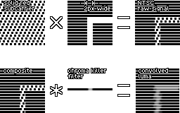
How an NTSC video signal gets generated in the PPU and decoded by the TV
Horizontal scale: 1 diagram pixel = 1 NTSC master clock (21.5 MHz) cycle; 4 diagram pixels = 1 NES pixel; 6 diagram pixels = 1 color subcarrier cycle
Top row: what goes on in the NES PPU
- Generate the subcarrier for a solid red screen (color $16).
- A shape drawn in this color, including a 2-pixel-wide vertical line.
- Multiply it by 0 outside of the shape and 1 inside the shape. Notice how the subcarrier protrudes into the shape.
Bottom row: what goes on in the TV when separating luma from chroma
- Incoming picture signal on the composite
- Impulse response of the low-pass filter
- Picture signal convolved with the low-pass filter, used as luma. Notice the ragged left and right sides of the vertical line.
The filter in this diagram is an FIR filter [1 4 7 8 8 8 7 4 1]/48, which factors to [1 1][1 1][1 1][1 1 1][1 0 0 1]/48. A real TV might use a Bessel filter (near-linear-phase IIR filter), but the principle is the same: filter out anything above 3 MHz.
Permission is granted to use this copyrighted illustration under the WTFPL.
File history
Click on a date/time to view the file as it appeared at that time.
| Date/Time | Thumbnail | Dimensions | User | Comment | |
|---|---|---|---|---|---|
| current | 21:56, 21 September 2021 | | 256 × 160 (2 KB) | >Maintenance script | == Summary == Importing file |
You cannot overwrite this file.
File usage
There are no pages that use this file.