File:Ntsc video timing.png: Difference between revisions
From NESdev Wiki
Jump to navigationJump to search
(A visualization of the NTSC PPU's video output signal, using different colors to denote each part of the signal. * Cyan is the horizontal blanking pulse * Dark blue is the "front porch" ** Yellow is the colorburst signal * Red is the visible output re...) |
(Clarify delay between internal PPU abstraction and output composite signal) |
||
| (8 intermediate revisions by 2 users not shown) | |||
| Line 1: | Line 1: | ||
A visualization of the NTSC PPU's video output signal, using different colors to denote each part of the signal. | A visualization of the NTSC PPU's video output signal, using different colors to denote each part of the signal. | ||
The video output of the PPU is delayed by 1 pixel clock; this means that cycle 0, scanline 0 according to the [https://www.nesdev.org/wiki/File:Ppu.svg PPU Frame Timing Diagram] is marked by the black pixel. | |||
* Cyan is the horizontal blanking pulse | * Cyan is the horizontal blanking pulse | ||
* Dark blue is the " | * Dark blue is the "back porch" after HBlank | ||
** Yellow is the colorburst signal | ** Yellow is the colorburst signal | ||
* Red is the visible output region, including the left and right border | * Red is the visible output region, including the left and right border | ||
** Bright green is the grayscale pulse (at cycle | ** Bright green is the grayscale pulse (at cycle 326) | ||
** Bright red is where the background and sprites are actually visible | ** Bright red is where the background and sprites are actually visible | ||
* Orange is the " | ** The orange dot is skipped on odd frames (340, 261) | ||
* Orange is the "front porch" before HBlank | |||
* Magenta is the vertical blanking pulse | * Magenta is the vertical blanking pulse | ||
* Dark green is the surrounding vertical blanking region (and the sync separator) | * Dark green is the surrounding vertical blanking region (and the sync separator) | ||
Latest revision as of 19:00, 11 April 2023
A visualization of the NTSC PPU's video output signal, using different colors to denote each part of the signal.
The video output of the PPU is delayed by 1 pixel clock; this means that cycle 0, scanline 0 according to the PPU Frame Timing Diagram is marked by the black pixel.
- Cyan is the horizontal blanking pulse
- Dark blue is the "back porch" after HBlank
- Yellow is the colorburst signal
- Red is the visible output region, including the left and right border
- Bright green is the grayscale pulse (at cycle 326)
- Bright red is where the background and sprites are actually visible
- The orange dot is skipped on odd frames (340, 261)
- Orange is the "front porch" before HBlank
- Magenta is the vertical blanking pulse
- Dark green is the surrounding vertical blanking region (and the sync separator)
File history
Click on a date/time to view the file as it appeared at that time.
| Date/Time | Thumbnail | Dimensions | User | Comment | |
|---|---|---|---|---|---|
| current | 10:57, 11 April 2023 |  | 341 × 262 (1 KB) | Persune (talk | contribs) | PPU dot skipped is off by 1 scanline |
| 08:09, 11 April 2023 |  | 341 × 262 (1 KB) | Persune (talk | contribs) | Remove uneccesary indicators; add cycle 0 dot indicator; fix dot skip indicator | |
| 21:56, 21 September 2021 | 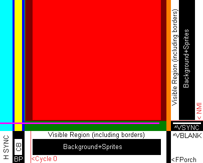 | 405 × 326 (3 KB) | >Maintenance script | == Summary == Importing file |
You cannot overwrite this file.
File usage
The following page uses this file: