NTSC video
Unlike many other game consoles, the NES does not generate RGB or YUV and then encode that to composite. Instead, it generates NTSC video directly in the composite domain, which leads to interesting artifacts.
Scanline Timing
The NTSC master clock is 21.47727273 MHz and each PPU pixel lasts four of these clocks: 186ns. (PAL is different. See PAL video.)
The values in this section are measured in PPU pixels, with 341 total per scanline.
The video output of the PPU is delayed by 1 pixel clock; this means that cycle 0, scanline 0 according to the PPU Frame Timing Diagram is marked by the black pixel.
The start times of each entry are thus relative to cycle 0, taking into account the delay. Timings based on Breaking NES Wiki reverse engineered horizontal[1] and vertical [2] decoder functions.
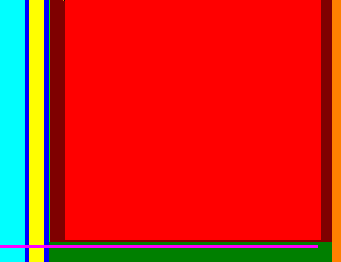
Rendering scanlines (n=240):
| ■ | name | start | duration | row | notes |
|---|---|---|---|---|---|
| ■ | horizontal sync | 277 | 25 | 0-239 | |
| ■ | back porch (black) | 302 | 4 | 0-239 | |
| ■ | colorburst | 306 | 15 | 0-239 | |
| ■ | back porch, continued (black) | 321 | 5 | 0-239 | |
| ■ | pulse (backdrop in grayscale) | 326 | 1 | 0-239 | one scanline earlier |
| ■ | left border (backdrop) | 327 | 15 | 0-239 | one scanline earlier; 14 pixels on end of row 261 for odd frames, if either background or sprite rendering is enabled |
| ■ | active | 1 | 256 | 0-239 | |
| ■ | right border (backdrop) | 257 | 11 | 0-239 | |
| ■ | front porch (black) | 268 | 9 | 0-239 |
Post-render scanlines (n=2):
| ■ | name | start | duration | row | notes |
|---|---|---|---|---|---|
| ■ | horizontal sync | 277 | 25 | 240-241 | |
| ■ | back porch (black) | 303 | 4 | 240-241 | |
| ■ | colorburst | 306 | 15 | 240-241 | |
| ■ | back porch, continued (black) | 321 | 5 | 240-241 | |
| ■ | pulse (backdrop in grayscale) | 326 | 1 | 240-241 | |
| ■ | bottom border (backdrop) | 327 | 282 | 240-241 | VBlank flag is set on scanline 241 |
| ■ | front porch (black) | 268 | 9 | 240-241 |
Post-render blanking scanlines (n=3):
| ■ | name | start | duration | row |
|---|---|---|---|---|
| ■ | horizontal sync | 277 | 25 | 242-244 |
| ■ | back porch (black) | 303 | 4 | 242-244 |
| ■ | colorburst | 306 | 15 | 242-244 |
| ■ | back porch, continued (black) | 321 | 5 | 242-244 |
| ■ | vertical blanking region (black) | 326 | 283 | 242-244 |
| ■ | front porch (black) | 268 | 9 | 242-244 |
Vertical sync scanlines (n=3):
| ■ | name | start | duration | row |
|---|---|---|---|---|
| ■ | vertical blanking pulse | 277 | 318 | 245-247 |
| ■ | vertical sync separator (black) | 254 | 14 | 245-247 |
| ■ | vertical sync separator (front porch, black) | 268 | 9 | 245-247 |
Pre-render blanking scanlines (n=14):
| ■ | name | start | duration | row | notes |
|---|---|---|---|---|---|
| ■ | horizontal sync | 277 | 25 | 248-261 | |
| ■ | back porch (black) | 303 | 4 | 248-261 | |
| ■ | colorburst | 306 | 15 | 248-261 | |
| ■ | back porch, continued (black) | 321 | 5 | 248-261 | |
| ■ | vertical blanking region (black) | 326 | 283 | 248-261 | VBlank is cleared on scanline 261 |
| ■ | front porch (black) | 268 | 9 | 248-261 |
This amounts to a total of 262 scanlines.
In standard NTSC, a scanline is 227.5 subcarrier cycles long (equivalent to 341.25 NES pixels), and each field is 262.5 scanlines lines tall. Vertical sync "serrations" or "equalization pulses" use a brief period of 31kHz horizontal sync to be able to start vertical sync half-way through a scanline, which makes the TV draw the next field one half scanline higher, resulting in interlaced video.
The video timing in the NES is non-standard - it both generates 341 pixels, making 227 1/3 subcarrier cycles per scanline, and always generates 262 scanlines. This causes the TV to draw the fields on top of each other, resulting in a non-standard low-definition "progressive" or "double struck" video mode sometimes called 240p.
Some high-definition displays and upscalers cannot handle 240p video, instead introducing artifacts that make the video appear as if it were interlaced. Artemio Urbina's 240p test suite, which has been ported to NES by Damian Yerrick, contains a set of test patterns to diagnose problems with decoding 240p composite video.
Note that emulators usually crop the top and bottom 8 lines from the picture, as most televisions will hide at least part of the picture in a similar way. See: Overscan
Brightness Levels
The NES's PPU's palette holds a set of 6-bit numbers, one for each simultaneous color displayable. In this section, we divide each palette entry into two halves, $xy. $x controls the brightness, and $y mostly controls the hue.
$xE/$xF output the same voltage as $1D. $x1-$xC output a square wave alternating between levels for $xD and $x0. Colors $20 and $30 are exactly the same.
When grayscale is active, all colors between $x1-$xD are treated as $x0. Notably this behavior extends to the first pixel of the border color, which acts as a sync pulse on every visible scanline.
Terminated measurement
Standard video (not NES) looks like this:
| Type | IRE level | Voltage (mV) |
|---|---|---|
| Peak white | 120 | |
| White | 100 | 714 |
| Colorburst H | 20 | 143 |
| Black | 7.5 | 53.6 |
| Blanking | 0 | 0 |
| Colorburst L | -20 | -143 |
| Sync | -40 | -286 |
The following measurements by lidnariq into a properly terminated (75 Ω) TV have about 10 mV of noise and 4 mV of quantization error, which implies an error of ±2 IRE:
| Signal | Potential | IRE |
|---|---|---|
| SYNC | 48 mV | -37 IRE |
| CBL | 148 mV | -23 IRE |
| 0D | 228 mV | -12 IRE |
| 1D | 312 mV | ≡ 0 IRE |
| CBH | 524 mV | 30 IRE |
| 2D | 552 mV | 34 IRE |
| 00 | 616 mV | 43 IRE |
| 10 | 840 mV | 74 IRE |
| 3D | 880 mV | 80 IRE |
| 20 | 1100 mV | 110 IRE |
| 0Dem | 192 mV | -17 IRE |
| 1Dem | 256 mV | -8 IRE |
| 2Dem | 448 mV | 19 IRE |
| 00em | 500 mV | 26 IRE |
| 10em | 676 mV | 51 IRE |
| 3Dem | 712 mV | 56 IRE |
| 20em | 896 mV | 82 IRE |
US NTSC is supposed to have a "setup", a difference between blanking and black level. Japanese NTSC does not. This means the exact same console will display slightly darker and with greater contrast on a US TV set than on a Japanese TV set.
Old measurement
This measurment table was added to the wiki in 2009. Its source is unknown, and its results differ from the terminated measurements above. This was used for Bisqwit's example C++ implementation below.
Voltage levels used by the PPU are as follows - absolute, relative to synch, and normalized between black level and white:
| Type | Absolute | Relative | Normalized |
|---|---|---|---|
| Synch | 0.781 | 0.000 | -0.359 |
| Colorburst L | 1.000 | 0.218 | -0.208 |
| Colorburst H | 1.712 | 0.931 | 0.286 |
| Color 0D | 1.131 | 0.350 | -0.117 |
| Color 1D (black) | 1.300 | 0.518 | 0.000 |
| Color 2D | 1.743 | 0.962 | 0.308 |
| Color 3D | 2.331 | 1.550 | 0.715 |
| Color 00 | 1.875 | 1.090 | 0.397 |
| Color 10 | 2.287 | 1.500 | 0.681 |
| Color 20 | 2.743 | 1.960 | 1.000 |
| Color 30 | 2.743 | 1.960 | 1.000 |
These levels don't quite match the standard levels. Ideally, the composite signal is 1000 millivolts from peak to peak (1.0 Vp-p) when loaded with a 75 Ω output impedance. (Unloaded levels may be twice that amount, which may explain the levels seen above.) Levels are commonly measured in units called IRE.[3][4]
Color Phases
111111------
22222------2
3333------33
444------444
55------5555
6------66666
------777777
-----888888-
----999999--
---AAAAAA---
--BBBBBB----
-CCCCCC-----
The color generator is clocked by the rising and falling edges of the ~21.48 MHz clock, resulting in an effective ~42.95 MHz clock rate. There are 12 color square waves, spaced at regular phases. Each runs at the ~3.58 MHz colorburst rate. Color $xY uses the wave numbered with Y in the table immediately above. NTSC colorburst (pure shade -U) is the same phase as phase 8.
PAL specifics are on PAL video.
Differential Phase Distortion
The output is subject to a differential phase distortion effect[5]. This causes a rotation of the NTSC signal's effective hue, proportional to the voltage, causing more shift for brighter colors. Current estimates approximate about 2.5° (2C02E) or 5° (2C02G) of additional rotation for each row of the palette.
The reason for this distortion is that the output impedance of the PPU is dependent on the signal level. When combined with the board's capacitance, it slows level transitions, causes the edges at high signal levels to be less steep. The high frequency chroma signal is sensitive to this, and the delay to its phase causes the hue rotation.
A PAL NES is affected by the same differential phase distortion, but because of the alternating-line mechanism of PAL, the effect is mostly cancelled out on consecutive scanlines.
Color Artifacts
Though it takes 12 clocks of the color generator mentioned above to complete a color cycle, an NTSC pixel is only 8 clocks wide, and a PAL pixel is 10 clocks wide. This means that the effective resolution of color is lower than the pixel resolution, and some color information has to be shared with a neighbouring pixel. This produces color errors at horizontal edges where the color changes. These errors are known as artifacts. They are especially noticeable as "shimmering" when the screen scrolls slowly.[6]
The phase alignment of each pixel to the color cycle changes on every scanline, and this affects the hue of each color artifact. E.g. if the "red" part of the cycle is outside the pixel, its error artifact will be a distortion of the red color.
An NTSC NES scanline is 227⅓ color cycles long, causing the alignment to shift by 4 clocks on each line. This creates a pattern of alignments that repeats every 3 lines. A vertical line may be seen to have a "rainbow" pattern of red, green, blue, red, green, blue... etc. The starting phase depends on a random alignment of the PPU to the picture which is determined on reset. (The scanline is shorter than standard NTSC, which has 227½ color cycles per line.)
A PAL NES scanline is 284⅙ color cycles long, instead causing the alignment to shift by 2 clocks on each line, with an additional temporary -3 clocks every second line to provide the phase-alternating-line mechanism. This creates a pattern of alignments that repeats every 6 lines. (The scanline is longer than standard PAL, which has 283¾ cycles per line.)
Each frame of the NTSC NES picture also starts from a changing alignment. Normally every odd frame is 1 dot shorter than every even frame, resulting in 59560⅔ color cycles on odd frames, and 59561⅓ on even frames. This creates a 2-frame repeating pattern, shifting by 8 clocks after an odd frame, then by 4 after an even one. The missing dot may be suppressed if rendering is disabled during the pre-render scanline, so some games which force blank through the top of the frame (e.g. Battletoads) advance the color phase alignment by 4 clocks every frame. In this case, it creates a 3-frame repeating pattern, which creates a more noticeable shimmering. See: PPU frame timing.
PAL and Dendy instead have an even number of color cycles per frame, so the color phase alignment does not change from frame to frame.
Color Tint Bits
There are three color modulation channels controlled by the top three bits of PPUMASK. Each channel uses one of the color square waves (see above diagram) and enables attenuation of the video signal when the color square wave is high. A single attenuator is shared by all channels. It is active for 6 out of 12 half-clocks if one bit is set, 10 half-clocks if two bits are set, or all 12 if all three bits are set.
| PPUMASK | Active phase | Active diagram | Complement |
|---|---|---|---|
| Bit 7 | Color 8 | -----888888- | Color 2 (blue) |
| Bit 6 | Color 4 | 444------444 | Color A (green) |
| Bit 5 | Color C | -CCCCCC----- | Color 6 (red) |
When attenuation is active and the current pixel is a color other than $xE/$xF (black), the signal is attenuated.
For example, when PPUMASK bit 6 is true, the attenuator will be active during the phases of color 4. This means the attenuator is not active during its complement (color A), and the screen appears to have a tint of color A, which is green.
Note that on the Dendy and PAL NES, the green and red bits swap meaning.
Tests performed on NTSC NES show that emphasis does not affect the black colors in columns $E or $F, but it does affect all other columns, including the blacks and greys in column $D.
The terminated measurements above suggest that resulting attenuated absolute voltage is approximately 0.81 times the un-attenuated absolute voltage.
The old measurement suggested a different approximation, applied to its relative or normalized values. This does not agree with the terminated measurements:
attenuated relative = relative * 0.746
attenuated normalized = normalized * 0.746 - 0.0912
Example Waveform
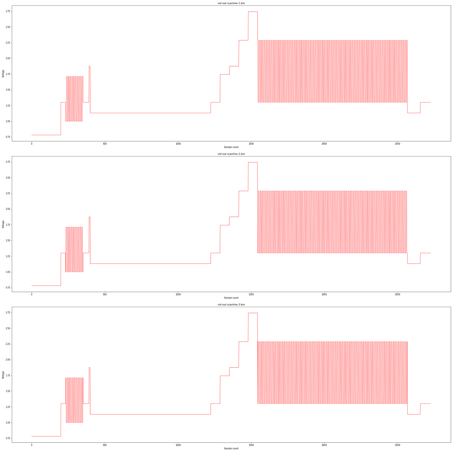
This waveform steps through various grays and then stops on a color.
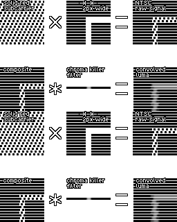
The PPU's shortcut method of NTSC modulation often produces artifacts in which vertical lines appear slightly ragged, as the chroma spills over into luma.
Composite decoding
Normal composite video encodes chroma and luma information into one composite analog signal. In order to convert composite into an RGB signal, it firsts needs to be decoded into YUV, before converting the resulting YUV into RGB.
The NES PPU does not encode anything into composite; instead, directly drawing the composite waveform itself. In order to convert the NES's composite signal into an RGB signal, it is decoded under the "assumption" that it was encoded under YUV.
YUV in this article refers to and will continue to refer to the equiband encoding of composite video as Y, b-y and r-y respectively. YIQ refers to the non-equiband encoding of composite, which has much more additional considerations regarding bandlimiting.
In practice, YIQ decoding is not used by any modern TV receiver and composite decoder, instead using YUV decoding as it is much simpler and less mathematically intensive to decode.[7][8]
Decoding composite video into YUV
Although encoding composite is somewhat standardized, the methods of decoding composite may vary from TV to TV. This article shows one way to decode composite.
Decoding luma information (Y)
To get the luma (Y) component, the base signal is filtered by a lowpass or comb filter. Some TVs use more complex methods to decode luma, some TVs do not filter at all.
Decoding chroma information (UV)
Decoding chroma information requires a subcarrier reference sine wave to determine the hue, whose phase is "locked" (or aligned as best as possible) to the colorburst of the composite scanline.
The subcarrier reference is used to demodulate the U component. A copy (or a phase offset) of the reference is delayed by 90 degrees, which is then used to demodulate the V component.
The U/V component is demodulated by multiplying the subcarrier reference to the composite waveform. The resulting waveform is then filtered typically by a lowpass filter. A comb filter can also be used if desired.
This demodulation, followed by lowpass filtering results in an average saturation loss of 50%. To account for this, most decoders multiply the resulting QAM demodulation by 2 before filtering.
Converting YUV to signal RGB
To convert YUV to signal RGB, we multiply the components to the following inversed matrix:
R = Y + V*1.14
G = Y - (R*0.299 - B*0.114) / 0.587
B = Y + U*2.03
Or, in terms of YUV only:
R = Y + V*1.14
G = Y - U*0.394242... - V*0.580681...
B = Y + U*2.03
The matrices above are derived from the NTSC base matrix[9] of luminance and color-difference:
  Y =  R*0.299 + G*0.587 + B*0.114
B-Y = -R*0.299 - G*0.587 + B*0.886
R-Y =  R*0.701 - G*0.587 - B*0.114
Which, when applied with the approximate color reduction factors 1/2.03 and 1/1.14 for B-Y and R-Y respectively[10], results in the definition of the linear RGB to YUV matrix equation:
Y =   R*0.299 + G*0.587 + B*0.114
U = (-R*0.299 - G*0.587 + B*0.886) / 2.03
V = ( R*0.701 - G*0.587 - B*0.114) / 1.14
In YIQ, the IQ component's chroma hue is just the UV component's chroma hue rotated by 33 degrees. Note that this is not precisely the same as properly decoding YIQ with different bandwidths for the I and Q component.
The following conversion is optional, and might match the look of other composite decoders:
U = -(I * sin(-33 deg)) + (Q * cos(-33 deg))
V =  (I * cos(-33 deg)) + (Q * sin(-33 deg))
Normalizing signals
After decoding, it is important to normalize the decoded RGB signals within the range of [0, 1].
Most TVs use the range 7.5 IRE to 100 IRE for normalizing the signal:
C = R, G, or B channel
signal_black_point = <voltage level $0F> + (7.5 / 140.0)
signal_white_point = <voltage level $0F> + (100. / 140.0)

C -= signal_black_point
C /= (signal_white_point - signal_black_point)
The 100 IRE white point may be substituted with voltage level $20 because on analog CRT TVs, the luma voltage does not strictly clip at a given level, with only the luminosity of the phosphors being the upper limit.
signal_white_point = <voltage level $20>
Similarly, some TVs do not use the 7.5 IRE setup black level, instead directly using the blank level.
signal_black_point = <voltage level $0F>
Finally, the signals must be clipped or normalized to [0, 1] to avoid values outside of the valid range.
C_raw  = R, G, or B channel
C_clip = clipped or normalized R, G, or B channel

C_clip = max(0, min(1, C_raw))
Converting signal RGB to display RGB
The final step is to convert signal RGB into the output colorspace, typically sRGB for most monitors.
Signal RGB into sRGB
Assuming no colorimetry involved, the resulting R, G and B values can directly be quantized into 8 bits per channel:
C'    = R, G or B signal
C8bpc = quantized R, G, or B channel

C8bpc = (int)(C' * 255)
However, if the signal RGB is assumed to be fed a reference display with different color primaries, then a correction matrix must be applied to the signal before quantization.
Emulating in C++ code
For efficient, ready to use implementations, see Libraries below. The following is an illustrative example. The values used are based on the "old" measurements given above.
Calculating the momentary NTSC signal level can be done as follows in C++:
// pixel = Pixel color (9-bit) given as input. Bitmask format: "eeellcccc".
// phase = Signal phase (0..11). It is a variable that increases by 8 each pixel.
float NTSCsignal(int pixel, int phase)
{
    // Voltage levels, relative to synch voltage
    static const float black=.518f, white=1.962f, attenuation=.746f,
        levels[8] = {.350f, .518f, .962f,1.550f,  // Signal low
                    1.094f,1.506f,1.962f,1.962f}; // Signal high

    // Decode the NES color.
    int color = (pixel & 0x0F);    // 0..15 "cccc"
    int level = (pixel >> 4) & 3;  // 0..3  "ll"
    int emphasis = (pixel >> 6);   // 0..7  "eee"
    if(color > 13) { level = 1;  } // For colors 14..15, level 1 is forced.

    // The square wave for this color alternates between these two voltages:
    float low  = levels[0 + level];
    float high = levels[4 + level];
    if(color == 0) { low = high; } // For color 0, only high level is emitted
    if(color > 12) { high = low; } // For colors 13..15, only low level is emitted

    // Generate the square wave
    auto InColorPhase = [=](int color) { return (color + phase) % 12 < 6; }; // Inline function
    float signal = InColorPhase(color) ? high : low;

    // When de-emphasis bits are set, some parts of the signal are attenuated:
    if( ((emphasis & 1) && InColorPhase(0))
    ||  ((emphasis & 2) && InColorPhase(4))
    ||  ((emphasis & 4) && InColorPhase(8)) ) signal = signal * attenuation;

    return signal;
}
The process of generating NTSC signal for a single pixel can be simulated with the following C++ code:
void RenderNTSCpixel(unsigned x, int pixel, int PPU_cycle_counter)
{
    int phase = PPU_cycle_counter * 8;
    for(int p=0; p<8; ++p) // Each pixel produces distinct 8 samples of NTSC signal.
    {
        float signal = NTSCsignal(pixel, phase + p); // Calculated as above
        // Optionally apply some lowpass-filtering to the signal here.
        // Optionally normalize the signal to 0..1 range:
        static const float black=.518f, white=1.962f;
        signal = (signal-black) / (white-black);
        // Save the signal for this pixel.
        signal_levels[ x*8 + p ] = signal;
    }
}
It is important to note that while the NES only generates eight (8) samples of NTSC signal per pixel, the wavelength for chroma is 12 samples long. This means that the colors of adjacent pixels get mandatorily mixed up to some degree. For the same reason, narrow black&white details can be interpreted as colors.
Because the scanline length is uneven (341*8 is not an even multiple of 12), the color mixing shifts a little each scanline. This appears visually as a sawtooth effect at the edges of colors at high resolution. The sawtooth cycles every 3 scanlines.
Because also the frame length is uneven (neither 262*341*8 nor (262*341-1)*8 is an even multiple of 12), the color mixing also changes a little every frame. When rendering is normally enabled, the screen is alternatingly 89342 and 89341 cycles long. The combination of these (89342+89341)*8 is an even multiple of 12, which means that the artifact pattern cycles every 2 frames. The pattern of cycling can be changed by disabling rendering during the end of the pre-render scanline; it forces the screen length to 89342 cycles, even if would be 89341 otherwise.
The process of decoding NTSC signal (convert it into RGB) is subject to a lot of study, and there are many patents and different techniques for it. A simple method suitable for emulation is covered below. It is not accurate, because in reality the chroma is blurred much more than is done here (the region of signal sampled for I and Q is wider than 12 samples), and the filter used here is a simple box FIR filter rather than an IIR filter, but it already produces a quite authentic looking picture. In addition, the border region (total of 26 pixels of background color around the 256-pixel scanline) is not sampled.
    float signal_levels[256*8] = {...}; // Eight signal levels for each pixel, normalized to 0..1 range.
Calculated as above.

    unsigned Width; // Input: Screen width. Can be not only 256, but anything up to 2048.
    float phase;    // Input: This should the value that was PPU_cycle_counter * 8 + 3.9
                    // at the BEGINNING of this scanline. It should be modulo 12.
                    // It can additionally include a floating-point hue offset.
    for(unsigned x = 0; x < Width; ++x)
    {
        // Determine the region of scanline signal to sample. Take 12 samples.
        int center = x * (256*8) / Width + 0;
        int begin = center - 6; if(begin < 0)     begin = 0;
        int end   = center + 6; if(end   > 256*8) end   = 256*8;
        float y = 0.f, i = 0.f, q = 0.f; // Calculate the color in YIQ.
        for(int p = begin; p < end; ++p) // Collect and accumulate samples
        {
            float level = signal_levels[p] / 12.f;
            y  =  y + level;
            i  =  i + level * cos( M_PI * (phase+p) / 6 );
            q  =  q + level * sin( M_PI * (phase+p) / 6 );
        }
        render_pixel(y,i,q); // Send the YIQ color for rendering.
    }
The NTSC decoder here produces pixels in YIQ color space.
If you want more saturated colors, just multiply i and q with a factor of your choosing, such as 1.7. If you want brighter colors, just multiply y, i and q with a factor of your choosing, such as 1.1. If you want to adjust the hue, just add or subtract a value from/to phase. If you want to see so called chroma dots, change the begin and end in such manner that you collect a number of samples that is not divisible with 12. If you want to blur the video horizontally, change the begin and end in such manner that the samples are collected from a wider region.
The YIQ colors can be converted into sRGB colors with the following formula, using the FCC-sanctioned YIQ-to-RGB conversion matrix. This produces a value that can be saved to e.g. framebuffer:
    float gamma = 2.0f; // Assumed display gamma
    auto gammafix = [=](float f) { return f <= 0.f ? 0.f : pow(f, 2.2f / gamma); };
    auto clamp    = [](int v) { return v>255 ? 255 : v; };
    unsigned rgb =
        0x10000*clamp(255.95 * gammafix(y +  0.946882f*i +  0.623557f*q))
      + 0x00100*clamp(255.95 * gammafix(y + -0.274788f*i + -0.635691f*q))
      + 0x00001*clamp(255.95 * gammafix(y + -1.108545f*i +  1.709007f*q));
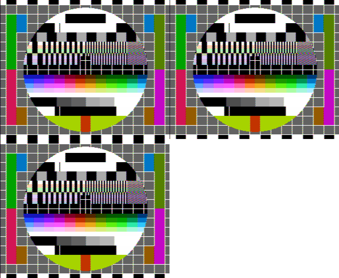
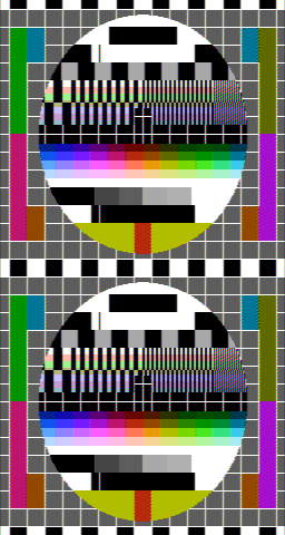
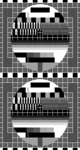
The two images below illustrate the NTSC artifacts.
In the left side image, 12 samples of NTSC signal were generated for each NES pixel,
and each display pixel was separately rendered by decoding that 12-sample signal.
In the right side image, 8 samples of NTSC signal were generated for each NES pixel,
and each display pixel was rendered by decoding 12 samples of NTSC signal from the
corresponding location within the scanline.
The source code of the program that generated both images can be read here: ntsc-small.cc. Note that even though the image resembles the well-known Philips PM5544 test card, it is not the same; the exact same colors could not be reproduced with NES colors. In addition, some parts were changed to better test NES features. For example, the backgrounds for the "station ID" regions (the black rectangles at the top and at the bottom inside the circle) are generated using the various blacks within the NES palette.
Later, Bisqwit made a generic integer-based decoder in C++. This takes a signal at 12 times color burst and can be used to emulate other systems that use shortcuts when generating NTSC video, such as Apple II (where every color in HGR is an artifact color) and Atari 7800 (whose game Tower Toppler seriously exploits artifact colors).
Libraries
- blargg's nes_ntsc library
- blargg's NTSC demo windows executable
- Forum thread: New NTSC decoder with integer-only math (short C++ code) - by Bisqwit
- LMP88959 (EMMIR)'s NTSC decoder
See also
References
- ↑ Breaking NES Wiki article on H counter decoder
- ↑ Breaking NES Wiki article on V counter decoder
- ↑ Tutorial 1184: Understanding Analog Video Signals
- ↑ Analog Video 101
- ↑ Re: In search of a PAL region reference palette - Explanation of the differential phase distortion of the NES.
- ↑ Effect of skipped dot on the picture - Forum thread with commentary and diagrams on the nature of color artifacts, and the skipped dot.
- ↑ S170m-2004.pdf: Composite Analog Video Signal NTSC for Studio Applications. Page 17.
- ↑ SMPTE EG 27-2004: Supplemental Information for SMPTE 170M and Background on the Development of NTSC Color Standards. Page 5.
- ↑ S170m-2004.pdf: Composite Analog Video Signal NTSC for Studio Applications. Page 4.
- ↑ S170m-2004.pdf: Composite Analog Video Signal NTSC for Studio Applications. Page 16.
