PPU registers: Difference between revisions
(Use fancy-schmancy line drawing characters) |
(Undo revision 6204 by Ulfalizer (talk): "fancy-schmancy line drawing characters" aren't in all fonts, and automatic substitution by the browser breaks monospace) |
||
| Line 14: | Line 14: | ||
Various flags controlling PPU operation | Various flags controlling PPU operation | ||
7654 3210 | 7654 3210 | ||
|||| |||| | |||
|||| ||++- Base nametable address | |||
|||| || (0 = $2000; 1 = $2400; 2 = $2800; 3 = $2C00) | |||
|||| |+--- VRAM address increment per CPU read/write of PPUDATA | |||
|||| | (0: increment by 1, going across; 1: increment by 32, going down) | |||
|||| +---- Sprite pattern table address for 8x8 sprites | |||
|||| (0: $0000; 1: $1000; ignored in 8x16 mode) | |||
|||+------ Background pattern table address (0: $0000; 1: $1000) | |||
||+------- Sprite size (0: 8x8; 1: 8x16) | |||
|+-------- PPU master/slave select | |||
+--------- Generate an [[NMI]] at the start of the | |||
[[wikipedia:Vertical blanking interval|vertical blanking interval]] (0: off; 1: on) | [[wikipedia:Vertical blanking interval|vertical blanking interval]] (0: off; 1: on) | ||
| Line 31: | Line 31: | ||
Equivalently, bits 0 and 1 are the most significant bit of the scrolling coordinates (see [[PPU_nametables|Nametables]] and [[#Scroll ($2005) >> write x2|PPU scroll]]): | Equivalently, bits 0 and 1 are the most significant bit of the scrolling coordinates (see [[PPU_nametables|Nametables]] and [[#Scroll ($2005) >> write x2|PPU scroll]]): | ||
7654 3210 | 7654 3210 | ||
|| | |||
|+- 1: Add 256 to the X scroll position | |||
+-- 1: Add 240 to the Y scroll position | |||
==== Note ==== | ==== Note ==== | ||
| Line 48: | Line 48: | ||
Write $1E when you're done to turn rendering back on. | Write $1E when you're done to turn rendering back on. | ||
The other bits do special effects with the colors. | The other bits do special effects with the colors. | ||
76543210 | |||
|||||||| | |||
|||||||+- Grayscale (0: normal color; 1: produce a monochrome display) | |||
||||||+-- 1: Show background in leftmost 8 pixels of screen; 0: Hide | |||
|||||+--- 1: Show sprites in leftmost 8 pixels of screen; 0: Hide | |||
||||+---- 1: Show background | |||
|||+----- 1: Show sprites | |||
||+------ Intensify reds (and darken other colors) | |||
|+------- Intensify greens (and darken other colors) | |||
+-------- Intensify blues (and darken other colors) | |||
When grayscale is turned on, the PPU ignores the lower nibble of each palette entry. | When grayscale is turned on, the PPU ignores the lower nibble of each palette entry. | ||
| Line 81: | Line 81: | ||
7654 3210 | 7654 3210 | ||
|||| |||| | |||
|||+-++++- Least significant bits previously written into a PPU register | |||
||| (due to register not being updated for this address) | |||
||+------- Sprite overflow. The intent was for this flag to be set | |||
|| whenever more than eight sprites appear on a scanline, but a | |||
|| hardware bug causes the actual behavior to be more complicated | |||
|| and generate false positives as well as false negatives; see | |||
|| [[PPU sprite evaluation]]. This flag is set during sprite | |||
|| evaluation and cleared at dot 1 (the second dot) of the | |||
|| pre-render line. | |||
|+-------- Sprite 0 Hit. Set when a nonzero pixel of sprite 0 overlaps | |||
| a nonzero background pixel; cleared at dot 1 of the pre-render | |||
| line. Used for raster timing. | |||
+--------- Vertical blank has started (0: not in VBLANK; 1: in VBLANK). | |||
Set at dot 1 of line 241 (the line *after* the post-render | Set at dot 1 of line 241 (the line *after* the post-render | ||
line); cleared after reading $2002 and at dot 1 of the | line); cleared after reading $2002 and at dot 1 of the | ||
Revision as of 13:17, 4 May 2013
The PPU exposes eight memory-mapped registers to the CPU. These nominally sit at $2000 through $2007 in the CPU's address space, but because they're incompletely decoded, they're mirrored in every 8 bytes from $2008 through $3FFF, so a write to $3456 is the same as a write to $2006.
Immediately after powerup, the PPU isn't necessarily in a usable state. The program needs to do a few things to get it going; see PPU power up state and Init code.
Controller ($2000) > write
Is often referred as PPUCTRL.
Various flags controlling PPU operation
7654 3210
|||| ||||
|||| ||++- Base nametable address
|||| ||    (0 = $2000; 1 = $2400; 2 = $2800; 3 = $2C00)
|||| |+--- VRAM address increment per CPU read/write of PPUDATA
|||| |     (0: increment by 1, going across; 1: increment by 32, going down)
|||| +---- Sprite pattern table address for 8x8 sprites
||||       (0: $0000; 1: $1000; ignored in 8x16 mode)
|||+------ Background pattern table address (0: $0000; 1: $1000)
||+------- Sprite size (0: 8x8; 1: 8x16)
|+-------- PPU master/slave select
+--------- Generate an NMI at the start of the
           vertical blanking interval (0: off; 1: on)
Setting bit 6 causes the PPU to output the lower four bits of the palette memory index on the EXT pins for each pixel (in addition to normal image drawing) - since only four bits are output, background and sprite pixels can't normally be distinguished this way. As the EXT pins are grounded on an unmodified NES, setting bit 6 is discouraged as it could potentially damage the chip whenever it outputs a non-zero pixel value (due to it effectively shorting VCC and GND together). Clearing bit 6 causes the PPU to instead read the background palette memory index to use for the background color from the EXT pins. This could be used by some device driving the PPU to replace the background with a different image. Normally the EXT pins are grounded, and the PPU will use palette color 0 for the background, as expected.
Equivalently, bits 0 and 1 are the most significant bit of the scrolling coordinates (see Nametables and PPU scroll):
7654 3210
       ||
       |+- 1: Add 256 to the X scroll position
       +-- 1: Add 240 to the Y scroll position
Note
Another way of seeing the explanation above is that when you reach the end of a nametable, you must switch to the next one, hence, changing the nametable address.
After power/reset, writes to this register are ignored for about 30000 cycles.
Mask ($2001) > write
Is often referred as PPUMASK.
This register controls screen enable, masking, and intensity. Write $00 here if you want to turn rendering off so that you can update the pattern tables or nametables outside of vertical blanking. Write $1E when you're done to turn rendering back on. The other bits do special effects with the colors.
76543210
||||||||
|||||||+- Grayscale (0: normal color; 1: produce a monochrome display)
||||||+-- 1: Show background in leftmost 8 pixels of screen; 0: Hide
|||||+--- 1: Show sprites in leftmost 8 pixels of screen; 0: Hide
||||+---- 1: Show background
|||+----- 1: Show sprites
||+------ Intensify reds (and darken other colors)
|+------- Intensify greens (and darken other colors)
+-------- Intensify blues (and darken other colors)
When grayscale is turned on, the PPU ignores the lower nibble of each palette entry. This causes a bitwise AND with $30 on any value read from PPU $3F00-$3FFF, both on the display and through PPUDATA ($2007). Writes to the palette through PPUDATA are not affected.
Hiding the leftmost 8 pixels is often done to cover artifacts from using horizontal scrolling with horizontal mirroring. Sprite 0 hit does not trigger in any area where the background or sprites are hidden. If both the background and sprites are hidden, the PPU enters "forced blank" state, where it stops rendering and releases control of the address and data bus.
NTSC video describes how bits D7-D5 (the "emphasis" bits or the "tint" bits) work on NTSC and PAL PPUs. Each bit's color have been confirmed on an NES; some older documents have them wrong. Caution: The RGB PPU (used on PlayChoice, Famicom Titler, and a couple Japanese TVs) treats the tint bits differently: instead of darkening other RGB components, it forces one RGB component to maximum brightness. A few games, which set all three tint bits to darken all colors, are unplayable on these PPUs. In either case, the tint bits are applied after grayscale, which means they still tint the gray image.
Status ($2002) < read
Is often referred as PPUSTATUS.
This register reflects the state of various functions inside the PPU. It is often used for determining timing. To determine when the PPU has reached a given pixel of the screen, put an opaque pixel of sprite 0 there.
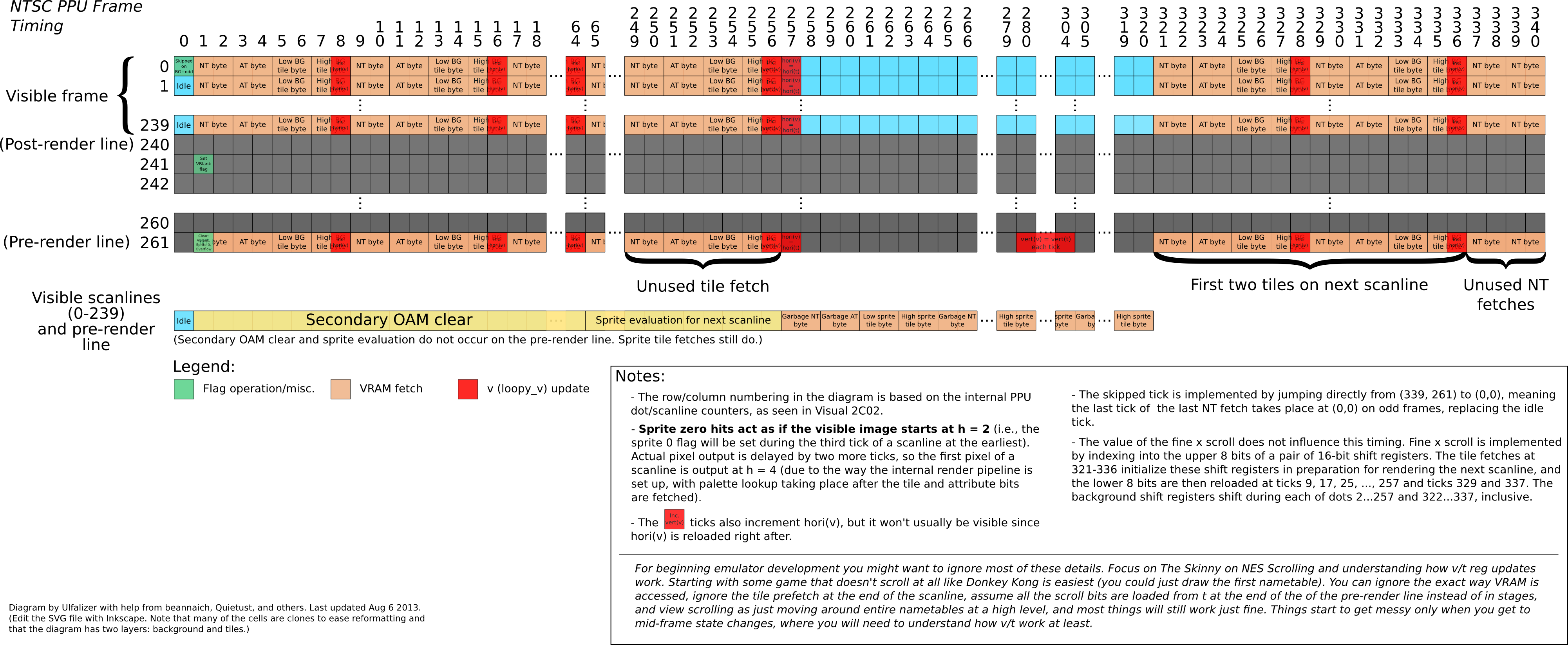
7654 3210
|||| ||||
|||+-++++- Least significant bits previously written into a PPU register
|||        (due to register not being updated for this address)
||+------- Sprite overflow. The intent was for this flag to be set
||         whenever more than eight sprites appear on a scanline, but a
||         hardware bug causes the actual behavior to be more complicated
||         and generate false positives as well as false negatives; see
||         PPU sprite evaluation. This flag is set during sprite
||         evaluation and cleared at dot 1 (the second dot) of the
||         pre-render line.
|+-------- Sprite 0 Hit.  Set when a nonzero pixel of sprite 0 overlaps
|          a nonzero background pixel; cleared at dot 1 of the pre-render
|          line.  Used for raster timing.
+--------- Vertical blank has started (0: not in VBLANK; 1: in VBLANK).
           Set at dot 1 of line 241 (the line *after* the post-render
           line); cleared after reading $2002 and at dot 1 of the
           pre-render line.
Notes
- Reading the status register will clear D7 mentioned above and also the address latch used by PPUSCROLL and PPUADDR.
- When the sprite 0 hit flag is set on a frame, it will not be cleared until the vertical blank has ended on the next frame. If attempting to use this flag for raster timing, it is important to ensure that the sprite 0 hit check happens outside of vertical blank, otherwise the CPU will "leak" through and the check will fail. The easiest way to do this is to place an earlier check for D6 = 0.
- This timing diagram might clarify the timing of setting and clearing the flags (source Inkscape SVG file).
- Caution: Reading PPUSTATUS at the exact start of vertical blank will return a 0 in D7 but clear the latch anyway, causing the program to miss frames. See NMI for details.
OAM address ($2003) > write
Is often referred as OAMADDR.
Write the address of OAM you want to access here. Most games just write $00 here and then use OAM_DMA ($4014). (DMA is implemented in the 2A03/7 chip and works by repeatedly writing $2004.)
Obscure details of OAMADDR
OAMADDR is set to 0 during each of ticks 257-320 (the sprite tile loading interval) of the pre-render and visible scanlines.
The value of OAMADDR when sprite evaluation starts at tick 65 of the visible scanlines will determine where in OAM sprite evaluation starts, and hence which sprite gets treated as sprite 0. The first OAM entry to be checked during sprite evaluation is the one starting at OAM[OAMADDR]. If OAMADDR is unaligned and does not point to the y position (first byte) of an OAM entry, then whatever it points to (tile index, attribute, or x coordinate) will be reinterpreted as a y position, and the following bytes will be similarly reinterpreted. No more sprites will be found once the end of OAM is reached, effectively hiding any sprites before OAM[OAMADDR].
Other oddities have been observed to occur when manually changing OAMADDR (as opposed to allowing it to auto-increment on writes to the data port), possibly related to the fact that OAM is made of dynamic memory which can decay into an "indeterminate" state (where bits are neither set nor clear) such that they could potentially inherit the state of other bits if OAMADDR is changed during the wrong clock phase. Whatever the actual glitchy behavior is, the Sachen game "Huge Insect" seems to rely on it.
OAM data ($2004) <> read/write
OAM data port, often referred as OAMDATA.
Write OAM data here. Writes will increment OAMADDR after the write; reads during vertical or forced blanking return the value from OAM at that address but do not increment.
Most games access this register through $4014 instead. Reading OAMDATA while the PPU is rendering will expose internal OAM accesses during sprite evaluation and loading; Micro Machines does this.
Note that reading OAM data isn't reliable in many cases, even when rendering is disabled. It is best to treat this as a write-only register.
Scroll ($2005) >> write x2
Is often referred as PPUSCROLL.
This register is used to change the scroll position, that is, to tell the PPU which pixel of the nametable selected through PPUCTRL should be at the top left corner of the rendered screen. Typically, this register is written to during VBlank, so that the next frame starts rendering from the desired location, but it can also be modified during rendering in order to split the screen. Changes made to the vertical scroll during rendering will only take effect on the next frame.
After reading PPUSTATUS to reset the address latch, write the horizontal and vertical scroll offsets here just before turning on the screen:
 bit PPUSTATUS
 ; possibly other code goes here
 lda cam_position_x
 sta PPUSCROLL
 lda cam_position_y
 sta PPUSCROLL
Horizontal offsets range from 0 to 255. "Normal" vertical offsets range from 0 to 239, while values of 240 to 255 are treated as -16 through -1 in a way, but tile data is incorrectly fetched from the attribute table.
By writing different values here across several frames and modifying the nametables accordingly one can achieve the effect of a camera panning over a large background.
Address ($2006) >> write x2
Is often referred as PPUADDR.
Because the CPU and the PPU are on separate buses, neither has direct access to the other's memory. The CPU writes to VRAM through a pair of registers on the PPU. First it loads an address into PPUADDR, and then it writes repeatedly to PPUDATA to fill VRAM.
After reading PPUSTATUS to reset the address latch, write the 16-bit address of VRAM you want to access here, upper byte first. For example, to set the VRAM address to $2108:
  lda #$21
  sta PPUADDR
  lda #$08
  sta PPUADDR
Valid addresses are $0000-$3FFF; higher addresses will be mirrored down.
note
Access to PPUSCROLL and PPUADDR during screen refresh produces interesting raster effects; the starting position of each scanline can be set to any pixel position in nametable memory. For more information, see The skinny on NES scrolling and tokumaru's sample code on the BBS.
Editor's note: Last comment about external page should be re-directed to the getting started section instead.
Data ($2007) <> read/write
Is often referred as PPUDATA.
VRAM read/write data register. After access, the VRAM address will increment by an amount determined by $2000:2.
When the screen is turned off by disabling the background/sprite rendering flag with the PPUMASK or during vertical blank, you can read or write data from VRAM through this port. Since accessing this register increments the VRAM address, it should not be accessed outside vblank when rendering is enabled, because it will cause graphical glitches, and if writing, write to an unpredictable address in VRAM.
The PPUDATA read buffer (post-fetch)
When reading while the VRAM address is in the range 0-$3EFF (i.e., before the palettes), the read will return the contents of an internal read buffer. This internal buffer is updated only when reading PPUDATA, and so is preserved across frames. After the CPU reads and gets the contents of the internal buffer, the PPU will immediately update the internal buffer with the byte at the current VRAM address. Thus, after setting the VRAM address, one should first read this register and discard the result.
Reading palette data from $3F00-$3FFF works differently. The palette data is placed immediately on the data bus, and hence no dummy read is required. Reading the palettes still updates the internal buffer though, but the data placed in it is the mirrored nametable data that would appear "underneath" the palette. (Checking the PPU memory map should make this clearer.)
See also: Reading 2007 during rendering